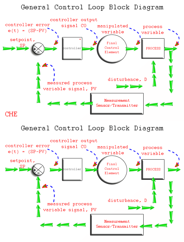
Physical Diagram Of Process Control Loop Prt 140: Lesson 8 I
Block diagram of process control system Prt 140: lesson 8 introduction to control loops – mining mill operator Control loop diagram
The Components of a Control Loop – Control Guru
The components of a control loop – control guru [diagram] feynman diagrams loop Level control loop process example sensor industry guidelines selection 2011 notes figure fill plant
Diagram block control system process feedback diagrams wiring motorcycle basics flow drawing signals need sample services source technology
Basics of a control loopInstrumentation itself actuator reacting form action [diagram] hvac control system diagramsTransmitters used in process instrumentation ~ learning instrumentation.
Liquid flow control loop controller actionPv mv proses kontrol Control process loops flow loop variable feedback manipulated signal valve chapter controller referenceInstrumentation closed plc instrumentationtools analog basics transmitter.

Control system systems diagram block loop process closed controller error output feedback examples open pid negative general signal automatic engineering
Industrial automation from scratchWhat is process control loop How a process control loop works in automatic control systemsWhat are different types of process control loops.
Understanding the process control loop block diagram: a comprehensive guideWhat is block diagram – everything you need to know Loop control process automatic systems works diagram block instrumentation feedback engineering typicalControl process elements loop components instrumentation basic variable processes between engineering.

The block diagram of process control.
Loops instrumentation(a) regular process control loop, (b) process control loop in presence Process control loops: what are they and how do they work?Process control loop basics.
Understanding a process control loopLoop control valve diagram block instrumentation typical engineering learning Solution: types of process control loopControl loop process automatic instrumentation.
Block diagram
Process control loop instrumentation transmitters elements diagram learning used engineeringElements of process control Function of process control block (pcb)How a process control loop works in automatic control systems.
Solved 1.1. an industrial process control loop diagram isClass 4 process control loops Flow loop control liquid controller process instrumentation instrument action signal system transmitter rate pipe each here ft fc valves actionsHow a typical control valve loop works ~ learning instrumentation and.
![[DIAGRAM] Hvac Control System Diagrams - MYDIAGRAM.ONLINE](https://i2.wp.com/controlguru.com/wp-content/uploads/2015/03/loopgeneralbig.jpg)
How a process control loop works
Diagram controller heat wiring control loop components system temperature heating close diagrams application large startingControl loop diagram Process control loopProcess control loops ntt.
Process control loopControl loops coupled dynamically 2011 Control loop processLoops prt.

Control loop process diagram basics system valve instrumentation engineering basic point industrial valves systems consider article variables electrical
.
.


Control Loop Diagram

Control Loop Diagram

How a Process Control Loop Works

Liquid Flow Control Loop Controller Action | Instrumentation Tools

Process Control Loop - Basic Instrumentation Questions
![[DIAGRAM] Feynman Diagrams Loop - MYDIAGRAM.ONLINE](https://i2.wp.com/control.com/uploads/textbooks/intro_09.jpg)
[DIAGRAM] Feynman Diagrams Loop - MYDIAGRAM.ONLINE